A) The element is a 25- resistor.
B) The element is a 35- resistor.
C) The element is a 0.45-H inductor.
D) The element is a 360-µF capacitor.
E) The element is a 510-µF capacitor.
G) B) and E)
Correct Answer

verified
Correct Answer
verified
Multiple Choice
An ac generator supplies a peak (not rms) voltage of 120.0 V at 60.0 Hz.It is connected in series with a 50.0- resistor and a 0.500-H inductor. -What is the rms voltage of the generator?
A) 84.9 V
B) 138 V
C) 151 V
D) 169 V
E) 240 V
G) B) and D)
Correct Answer

verified
Correct Answer
verified
Multiple Choice
A variable inductor is connected to an ac source.What effect does increasing the inductance have on the reactance and current in this circuit? 
A) ![]()
B) ![]()
C) ![]()
D) ![]()
E) ![]()
G) A) and D)
Correct Answer

verified
Correct Answer
verified
Multiple Choice
In an ac circuit, a 0.055-H inductor is connected to a generator that has an rms voltage of 18 V and operates at 50.0 Hz.What is the rms current through the inductor?
A) 0.62 A
B) 2.0 A
C) 3.2 A
D) 1.0 A
E) 14 A
G) C) and E)
Correct Answer

verified
Correct Answer
verified
Multiple Choice
The voltage across and the current through a single circuit element connected to an ac generator are shown in the graph. 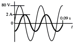 -Note the following circuit elements: (1) resistors, (2) capacitors, and (3) inductors.Which of these elements uses no energy, on average, in an ac circuit?
A) 1 only
B) 2 only
C) 3 only
D) both 2 and 3
E) both 1 and 3
G) A) and C)
Correct Answer

verified
D
Correct Answer
verified
Multiple Choice
An ac generator supplies a peak (not rms) voltage of 150 V at 60.0 Hz.The generator is connected in series with a 35-mH inductor, a 45-µF capacitor and an 85- resistor. -Determine the rms current in the circuit.
A) 0.28 A
B) 0.40 A
C) 0.75 A
D) 1.1 A
E) 1.6 A
G) B) and C)
Correct Answer

verified
Correct Answer
verified
Multiple Choice
An ac generator supplies an rms (not peak) voltage of 180 V at 60.0 Hz.The generator is connected in series with a 0.50-H inductor, a 6.0-µF capacitor and a 300- resistor. -What is the impedance of the circuit?
A) 150
B) 190
C) 360
D) 390
E) 440
G) A) and B)
Correct Answer

verified
Correct Answer
verified
Multiple Choice
An ac generator supplies a peak (not rms) voltage of 150 V at 60.0 Hz.The generator is connected in series with a 35-mH inductor, a 45-µF capacitor and an 85- resistor. -Which one of the following statements concerning this circuit is true?
A) The voltage leads the current.
B) The circuit is more capacitive than inductive.
C) The voltage and current are exactly out of phase.
D) The voltage and current are in phase.
E) The phase angle for this circuit is positive.
G) A) and C)
Correct Answer

verified
Correct Answer
verified
Multiple Choice
An ac circuit consists of a series combination of an inductor and a capacitor.What is the phase angle between the voltages across these two circuit elements?
A) 0°
B) 90°
C) 180°
D) 270°
E) 360°
G) B) and E)
Correct Answer

verified
Correct Answer
verified
Multiple Choice
An ac generator supplies an rms (not peak) voltage of 180 V at 60.0 Hz.The generator is connected in series with a 0.50-H inductor, a 6.0-µF capacitor and a 300- resistor. -What is the peak (not rms) voltage across the capacitor?
A) 120 V
B) 180 V
C) 190 V
D) 210 V
E) 290 V
G) C) and D)
Correct Answer

verified
Correct Answer
verified
Multiple Choice
An oscillating LC circuit has a resonant frequency of 1.2 × 10⁶ Hz.The diagram shows the system at t = 0 s when there is no charge on the capacitor and the current is in the direction shown.At this time, the energy stored in the inductor is 2.5 × 10⁻⁷ J. 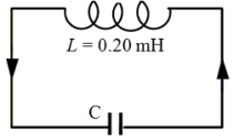 -Determine the numerical value of the capacitance.
A) 2.4 × 10⁻¹¹ F
B) 3.6 × 10⁻¹¹ F
C) 4.4 × 10⁻¹¹ F
D) 6.8 × 10⁻¹¹ F
E) 8.8 × 10⁻¹¹ F
G) B) and C)
Correct Answer

verified
Correct Answer
verified
Multiple Choice
Which one of the following graphs shows how the inductive reactance varies with frequency? 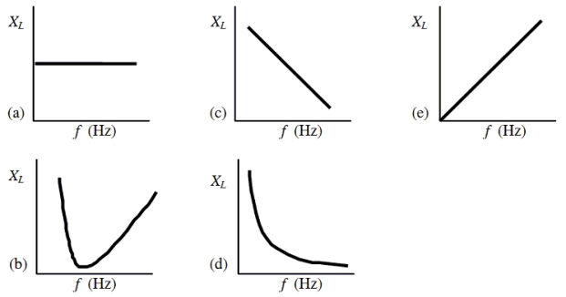
A) a
B) b
C) c
D) d
E) e
G) D) and E)
Correct Answer

verified
Correct Answer
verified
Multiple Choice
The table below shows the values of the resistance, capacitive reactance and inductive reactance for five RCL circuits.In which circuit will the voltage lead the current? 
A) ![]()
B) ![]()
C) ![]()
D) ![]()
E) ![]()
G) B) and D)
Correct Answer

verified
Correct Answer
verified
Multiple Choice
The reactance of a capacitor in a circuit at 110 Hz is 35 .Determine the capacitance.
A) 41 µF
B) 260 µF
C) 51 mF
D) 0.10 F
E) 0.31 F
G) B) and E)
Correct Answer

verified
Correct Answer
verified
Multiple Choice
An ac generator supplies an rms (not peak) voltage of 180 V at 60.0 Hz.The generator is connected in series with a 0.50-H inductor, a 6.0-µF capacitor and a 300- resistor. -What is the peak (not rms) voltage across the inductor?
A) 120 V
B) 180 V
C) 190 V
D) 260 V
E) 290 V
G) B) and E)
Correct Answer

verified
Correct Answer
verified
Multiple Choice
The graph shows the voltage across and the current through a single circuit element connected to an ac generator. 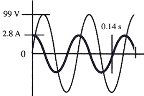 -What is the reactance of this element?
A) 20
B) 25
C) 30
D) 35
E) 40
G) A) and B)
Correct Answer

verified
Correct Answer
verified
Multiple Choice
The graph shows the impedance as a function of frequency for a series RCL circuit.At what frequency does the capacitor make the largest contribution? 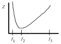
A) f1
B) f2
C) f3
D) f1 or f3
E) f1 or f2 or f3
G) A) and D)
Correct Answer

verified
A
Correct Answer
verified
Multiple Choice
An ac generator supplies a peak (not rms) voltage of 120.0 V at 60.0 Hz.It is connected in series with a 50.0- resistor and a 0.500-H inductor. -What is the peak current through the resistor?
A) 2.40 A
B) 1.71 A
C) 1.33 A
D) 0.617 A
E) 0.437 A
G) A) and B)
Correct Answer

verified
D
Correct Answer
verified
Multiple Choice
Which one of the following graphs illustrates how capacitive reactance varies with frequency? 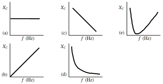
A) a
B) b
C) c
D) d
E) e
G) All of the above
Correct Answer

verified
Correct Answer
verified
Multiple Choice
For which one of the following circuit arrangements will the power factor be non-zero?
A) a capacitor in series with an ac generator
B) an inductor in series with an ac generator
C) two capacitors in series with an ac generator
D) a capacitor and resistor in series with an ac generator
E) a capacitor and inductor in series with an ac generator
G) C) and D)
Correct Answer

verified
Correct Answer
verified
Showing 1 - 20 of 84
Related Exams